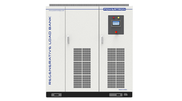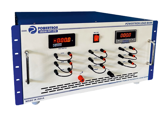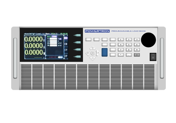

Regenerative Load Bank Manufacturers & Exporters
POWERTRON manufactures regenerative load bank systems in India from 60kW to 250kW, covering 10-1000V and up to 1000A, for test facilities where dissipating the test energy as heat is no longer acceptable. A conventional resistive load bank converts every watt of test power into heat that then has to be extracted from the building. A regenerative load bank instead returns that energy to the grid through a four-quadrant PWM converter, at better than 93% efficiency and 0.99 power factor, with input harmonics held under 3%. On a battery, EV or drive test bench running continuously, that is the difference between paying twice for the same energy and paying once. High-speed digital control delivers 0.1% output accuracy across constant resistance, voltage, current and power modes, and the modular construction allows capacity to be added without replacing the installation. Manufactured in-house at Wagle Estate, Thane, Maharashtra.
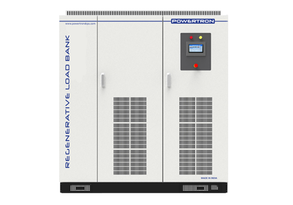




Technical Specifications — Regenerative Load Bank
| Parameter | Specification | What It Means For You |
|---|---|---|
| Power Range | 60, 80, 100, 120, 150, 200 and 250 kW | Component bench through to full pack and drive-level test cells |
| Voltage Range | 10–600V, 10–800V and 10–1000V by model | Covers 400V and 800V EV architectures and industrial DC buses |
| Rated Current | 600A, 800A and 1000A | Current rating selected independently of voltage and power |
| Energy Flow | Four-quadrant, bidirectional, grid-returning | Test energy recovered instead of dissipated as heat |
| Efficiency | Greater than 93% | Under 7% of test energy lost rather than 100% |
| Power Factor | 0.99 via PWM rectification | No penalty on the facility supply, no correction equipment needed |
| Input Harmonics | Less than 3% | Compliant behaviour on the incoming grid connection |
| Operating Modes | Constant resistance, voltage, current and power | One instrument covers battery, drive, inverter and PSU testing |
| Accuracy | 0.1% output accuracy, high-speed digital control | Loading condition matches the test specification exactly |
| Transient Response | Fast response across all four modes | Dynamic load profiles reproduced, not just static steps |
| Compensation | Automatic line voltage drop compensation | Programmed condition delivered at the DUT terminals |
| Interface | 10-inch touchscreen | Single-screen operation of a multi-mode instrument |
| Components | LEM sensing, Infineon power devices | Internationally sourceable spares |
| Construction | Modular | Scalable capacity and module-level maintenance |
Available Variants
| Model number | Rated Power | Voltage Range | Rated Current |
|---|---|---|---|
| PIPL-150-800-600-RLB | 150kW | 10~800V | 600A |
| PIPL-150-800-800-RLB | 10~800V | 800A | |
| PIPL-150-800-1000-RLB | 10~800V | 1000A | |
| PIPL-150-1000-600-RLB | 10~1000V | 600A | |
| PIPL-150-1000-800-RLB | 10~1000V | 800A | |
| PIPL-150-1000-1000-RLB | 410~1000V | 1000A | |
| PIPL-200-800-600-RLB | 200kW | 10~800V | 600A |
| PIPL-200-800-800-RLB | 10~800V | 800A | |
| PIPL-200-800-1000-RLB | 10~800V | 1000A | |
| PIPL-200-1000-600-RLB | 10~1000V | 600A | |
| PIPL-200-1000-800-RLB | 10~1000V | 800A | |
| PIPL-200-1000-1000-RLB | 10~1000V | 1000A | |
| PIPL-250-800-600-RLB | 250kW | 10~800V | 600A |
| PIPL-250-800-800-RLB | 10~1000V | 800A | |
| PIPL-250-800-1000-RLB | 10~800V | 1000A | |
| PIPL-250-1000-600-RLB | 10~1000V | 600A | |
| PIPL-250-1000-800-RLB | 10~1000V | 800A | |
| PIPL-250-1000-1000-RLB | 10~1000V | 1000A | |
| PIPL-060-600-600-RLB | 60kW | 10~600V | 600A |
| PIPL-060-600-800-RLB | 10~600V | 800A | |
| PIPL-060-600-1000-RLB | 10~600V | 1000A | |
| PIPL-060-1000-600-RLB | 10~1000V | 600A | |
| PIPL--060-1000-800-RLB | 10~1000V | 800A | |
| PIPL-060-1000-1000-RLB | 10~1000V | 1000A | |
| PIPL-080-800-600-RLB | 80kW | 10~800V | 600A |
| PIPL-080-800-800-RLB | 10~800V | 800A | |
| PIPL-080-800-1000-RLB | 10~800V | 1000A | |
| PIPL-080-1000-600-RLB | 10~1000V | 600A | |
| PIPL-080-1000-800-RLB | 10~1000V | 800A | |
| PIPL-080-1000-1000-RLB | 10~1000V | 1000A | |
| PIPL-080-800-600-RLB | 100kW | 10~800V | 600A |
| PIPL-080-800-800-RLB | 10~800V | 800A | |
| PIPL-080-800-1000-RLB | 10~800V | 1000A | |
| PIPL-080-1000-600-RLB | 10~1000V | 600A | |
| PIPL-080-1000-800-RLB | 10~1000V | 800A | |
| PIPL-080-1000-1000-RLB | 10~1000V | 1000A | |
| PIPL-120-800-600-RLB | 120kW | 10~800V | 600A |
| PIPL-120-800-800-RLB | 10~800V | 800A | |
| PIPL-120-800-1000-RLB | 10~800V | 1000A | |
| PIPL-120-1000-600-RLB | 10~1000V | 600A | |
| PIPL-120-1000-800-RLB | 10~1000V | 800A | |
| PIPL-120-1000-1000-RLB | 10~1000V | 1000A |
Which Regenerative Load Bank Do You Need?
| Power | Voltage Options | Current | Typical Application |
|---|---|---|---|
| 60 kW | 10–600V, 10–1000V | 600 / 800 / 1000 A | Module-level battery testing, small drive and inverter validation |
| 80 kW | 10–800V, 10–1000V | 600 / 800 / 1000 A | Battery pack testing, mid-size drive loading, PSU qualification |
| 100 kW | 10–800V, 10–1000V | 600 / 800 / 1000 A | EV pack cycling, renewable inverter testing, telecom rectifier plant |
| 120 kW | 10–800V, 10–1000V | 600 / 800 / 1000 A | Traction component loading, larger inverter and converter testing |
| 150 kW | 10–800V, 10–1000V | 600 / 800 / 1000 A | Vehicle-level EV testing, railway sub-system loading |
| 200 kW | 10–800V, 10–1000V | 600 / 800 / 1000 A | High-power drive and traction test cells, grid-tie equipment testing |
| 250 kW | 10–800V, 10–1000V | 600 / 800 / 1000 A | Full test facility installations, multi-station laboratories |
How a Regenerative Load Bank Works
A regenerative load bank presents itself to the device under test as a programmable load, exactly as a resistive bank would — but what happens to the energy afterwards is completely different. Instead of routing it into resistor elements and turning it into heat, the load bank draws it into a DC stage and then feeds it back into the AC grid through a four-quadrant PWM converter operating in reverse.
The four-quadrant description is the key. A conventional rectifier moves power in one direction only, from AC to DC. A four-quadrant converter handles both current directions at both voltage polarities, which means the same power stage that would draw energy from the grid can equally push energy into it. The controller keeps the returned current synchronised and in phase with the grid, which is what produces the 0.99 power factor and holds input harmonics below 3%.
On the load side, a high-speed digital control loop samples voltage and current continuously and adjusts the converter to hold whichever mode is programmed. In constant resistance mode it holds the ratio of voltage to current; in constant current it holds current regardless of voltage; in constant power it trades the two off; in constant voltage it holds terminal voltage. Switching between modes is a firmware operation, not a hardware change.
The economic consequence is straightforward. A 250kW resistive bank running eight hours consumes 2,000 kWh and produces 2,000 kWh of heat the building must then remove. The same test on a regenerative bank at 93% efficiency returns roughly 1,860 kWh to the grid and produces only the balance as heat.
Applications of Regenerative Load Banks
Regenerative load banks are justified wherever test duty is long, repetitive or high-power — the payback comes from hours of operation, not from the purchase. Short, occasional commissioning tests are usually better served by a resistive bank.
| Industry | Application | Mode Used | Typical Power |
|---|---|---|---|
| Battery Manufacturing & Testing | Pack and module discharge cycling, capacity verification | CC / CP | 60–250 kW |
| Automotive & EV | Traction battery, inverter and charger loading | CP / CR | 100–250 kW |
| Aerospace | Generator and power system qualification loading | CC / CV | 60–150 kW |
| Railway & Metro | Traction converter and auxiliary supply loading | CP | 150–250 kW |
| Power Electronics R&D | Converter, inverter and PSU characterisation | All four modes | 60–120 kW |
| Telecom & Data Centre | Rectifier plant and UPS discharge testing | CC / CR | 60–200 kW |
| Solar & Wind | Inverter and grid-tie equipment validation | CP / CV | 100–250 kW |
| Petrochemical | Emergency generator and DC system commissioning | CR / CP | 100–250 kW |
Regenerative vs Resistive vs Programmable Load Bank
| Criteria | Regenerative Load Bank | Resistive Load Bank | Programmable Load Bank |
|---|---|---|---|
| Energy handling | Returned to the grid | Dissipated as heat | Dissipated as heat |
| Efficiency | Over 93% recovered | Zero recovery | Zero recovery |
| Heat rejection | Minimal | Full test power as heat | Full test power as heat |
| Running cost | Lowest over long duty | Highest | Moderate |
| Capital cost | Highest | Lowest | Moderate |
| Control modes | CR, CV, CC, CP | Fixed steps | CV, CC, CR, CP |
| Power range | 60–250 kW | Custom, very high | 1.2–40 kW |
| Dynamic response | Fast | Step switching only | Up to 10 kHz dynamic |
| Best fit | Long-duration, high-power, repetitive testing | Commissioning, generator and UPS proving | Bench and component-level electronic loading |
Manufacturing, Quality and Export Capability
POWERTRON INDIA PVT. LTD. designs and manufactures its complete power conversion range at Plot No. A-426/427, Road No. 28, Wagle Estate MIDC, Thane West 400604, Maharashtra. Design, magnetics, PCB assembly, enclosure fabrication and full-load testing are all carried out in-house, which is what allows both short lead times and real engineering support after the sale rather than component-level replacement only.
Every unit is tested on load across its full operating envelope before dispatch, with the test record supplied against the serial number. The company holds ISO, CE and BIS certifications, is MSME registered and GeM listed, and manufactures under the Make in India framework — making POWERTRON a practical import substitute for organisations currently sourcing from overseas. Domestic sales and service offices operate in Delhi, Pune, Hyderabad, Bangalore and Tamil Nadu, with international offices in Dubai, Singapore and Malaysia supporting export customers across the Middle East, Southeast Asia, Africa and Europe.
Frequently Asked Questions — Regenerative Load Bank
Both present a controlled load to the equipment under test. A resistive load bank turns all of that energy into heat. A regenerative load bank returns it to the AC grid through a four-quadrant converter at better than 93% efficiency, so the facility neither pays for the energy twice nor has to extract the heat.
Better than 93% of test energy is returned. On a 250kW unit running an eight-hour shift, that is roughly 1,860 kWh of the 2,000 kWh consumed returned to the grid, with only the balance appearing as heat.
Standard models cover 60, 80, 100, 120, 150, 200 and 250kW, with voltage ranges of 10-600V, 10-800V and 10-1000V, and rated currents of 600A, 800A and 1000A. Higher ratings are built to order.
Constant resistance, constant voltage, constant current and constant power, all with fast transient response and 0.1% output accuracy. Switching between modes is a firmware operation, so one unit covers battery discharge, drive loading, inverter testing and power supply validation.
PWM rectification gives a 0.99 power factor and holds input harmonics below 3%, so the unit behaves as a well-mannered load and source on the incoming supply rather than as a harmonic problem the facility then has to correct.
Requirements vary by distribution licensee. Some require notification or approval for equipment that exports even at low duty. Raise this with your electricity supplier early, and the POWERTRON team can supply the technical documentation the application needs.
Yes, and it is one of the primary applications. Constant current and constant power modes with programmable protection thresholds allow controlled discharge cycling of packs and modules, with the discharge energy recovered rather than dissipated — which matters when a single characterisation run takes hours.
Yes. Construction is modular, so a facility can commission at one rating and add modules as test demand grows without replacing the installation. The same modularity means maintenance can be done at module level.
It depends entirely on daily operating hours and local electricity tariff, since the saving accrues per kWh of test energy. Facilities running long-duration battery or drive testing typically see the shortest payback. Share your duty cycle and tariff and POWERTRON can work the calculation with you.
Need a Regenerative Load bank?
Request a quotation for a regenerative load bank. Send your maximum test power and voltage, peak current, required control modes, daily duty cycle and grid connection details to sales@powertrondcps.com, or call +91 8097707496 / +91 7208560460. POWERTRON quotes standard models from 60kW to 250kW and custom builds above.