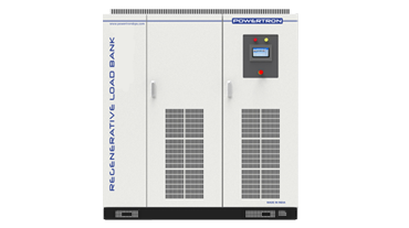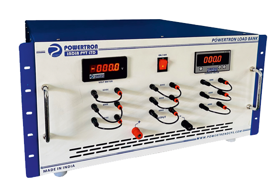

Programmable Load Bank Manufacturers & Exporters
POWERTRON manufactures programmable load bank and electronic load systems in India from 1.2kW to 40kW, covering 0-150V, 0-600V, 0-800V and 0-1200V input ranges with currents to 1200A. Where a resistive bank offers fixed switched steps, a programmable electronic load holds any loading condition the test requires under digital control — constant voltage, constant current, constant resistance or constant power — and switches between them in firmware rather than hardware. Dynamic mode operates to 10kHz, which is fast enough to reproduce the load transients a switch-mode power supply or converter will actually see in service rather than only the steady states. Measurement resolution reaches 0.1mV and 0.1mA, with remote sense correcting for cable drop at the terminals. Dedicated battery test, OPP, OCP, automatic test and CR-LED functions cover the routine qualification sequences directly. Manufactured in-house at Wagle Estate, Thane, Maharashtra.
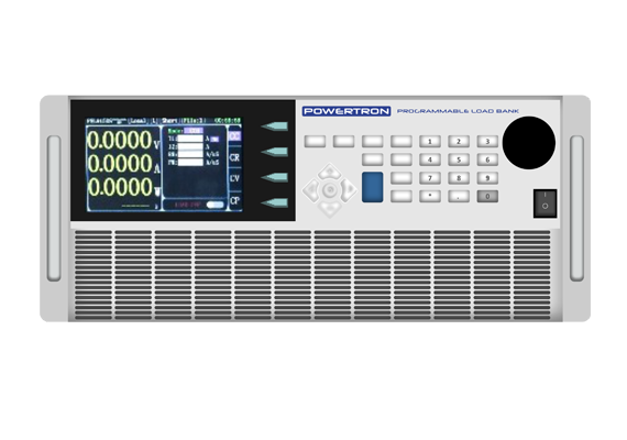





Technical Specifications — Programmable Electronic Load
| Parameter | Specification | What It Means For You |
|---|---|---|
| Power Range | 1.2 kW to 40 kW | Bench component testing through to system-level loading |
| Voltage Ranges | 0–150V, 0–600V, 0–800V, 0–1200V | Low-voltage electronics through to 800V EV and 1000V+ DC bus |
| Current Range | Up to 1200 A depending on model | High-current low-voltage loading as well as high-voltage work |
| Operating Modes | CV, CC, CR, CP | One instrument covers PSU, battery, converter and LED testing |
| Dynamic Mode | Up to 10 kHz | Real load transients reproduced, not just static steps |
| Measurement Resolution | 0.1 mV / 0.1 mA | Regulation and ripple behaviour resolved rather than averaged |
| Remote Sense | Standard | Load condition held at the DUT terminals, not the load input |
| Test Functions | Battery test, automatic test, OPP, OCP, CR-LED | Standard qualification routines run directly |
| Short Circuit Function | Standard | Controlled short-circuit response testing |
| Current Monitoring | Standard | Live current readback for logging and verification |
| Memory | Power-off memory, 100 group storage | Set-ups survive power cycling; fast recall on a production line |
| Interfaces | Optional USB / RS232 / RS485 | Integration with existing test automation |
| Model Naming | PIPL-[power]-[voltage]-[current]-PEL | Rating readable directly from the part number |
Available Variants
| Model | Voltage | Current | Power | Model | Voltage | Current | Power | |
|---|---|---|---|---|---|---|---|---|
| PIPL-1K2-150-120-PEL | 0-150V | 120A | 1200W | PIPL-1K2-800-120-PEL | 0-800V | 48A | 1200W | |
| PIPL-1K8-150-180-PEL | 0-150V | 180A | 1800W | PIPL-1K8-800-72-PEL | 0-800V | 72A | 1800W | |
| PIPL-2K4-150-2K4-PEL | 0-150V | 2400A | 2400W | PIPL-2K4-800-96-PEL | 0-800V | 96A | 2400W | |
| PIPL-3K-150-300-PEL | 0-150V | 300A | 3000W | PIPL-3K-800-120-PEL | 0-800V | 120A | 3000W | |
| PIPL-6K-150-600-PEL | 0-150V | 600A | 6000W | PIPL-6K-800-240-PEL | 0-800V | 240A | 6000W | |
| PIPL-9K-150-900-PEL | 0-150V | 900A | 9000W | PIPL-9K-800-360-PEL | 0-800V | 360A | 9000W | |
| PIPL-12K-150-1K2-PEL | 0-150V | 1200A | 12KW | PIPL-12K-800-480-PEL | 0-800V | 480A | 12KW | |
| PIPL-15K-150-1K5-PEL | 0-150V | 1500A | 15KW | PIPL-15K-800-800-PEL | 0-800V | 600A | 15KW | |
| PIPL-18K-150-1K2-PEL | 0-150V | 1200A | 18KW | PIPL-18K-800-720-PEL | 0-800V | 720A | 18KW | |
| PIPL-24K-150-1K2-PEL | 0-150V | 1200A | 24KW | PIPL-24K-800-960-PEL | 0-800V | 960A | 24KW | |
| PIPL-30K-150-1K2-PEL | 0-150V | 1200A | 30KW | PIPL-30K-800-1K2-PEL | 0-800V | 1200A | 30KW | |
| PIPL-40K-150-1K2-PEL | 0-150V | 1200A | 40KW | PIPL-40K-800-1K2-PEL | 0-800V | 1200A | 40KW | |
| PIPL-3K-1K2-120-PEL | 0-1K2V | 120A | 3000W | PIPL-1K2-600-120-PEL | 0-600V | 48A | 1200W | |
| PIPL-6K-1K2-240-PEL | 0-1K2V | 240A | 6000W | PIPL-1K8-600-72-PEL | 0-600V | 72A | 1800W | |
| PIPL-9K-1K2-360-PEL | 0-1K2V | 360A | 9000W | PIPL-2K4-600-96-PEL | 0-600V | 96A | 2400W | |
| PIPL-12K-1K2-480-PEL | 0-1K2V | 480A | 12KW | PIPL-3K-600-120-PEL | 0-600V | 120A | 3000W | |
| PIPL-15K-1K2-1K2-PEL | 0-1K2V | 600A | 15KW | PIPL-6K-600-240-PEL | 0-600V | 240A | 6000W | |
| PIPL-18K-1K2-720-PEL | 0-1K2V | 720A | 18KW | PIPL-9K-600-360-PEL | 0-600V | 360A | 9000W | |
| PIPL-24K-1K2-960-PEL | 0-1K2V | 960A | 24KW | PIPL-12K-600-480-PEL | 0-600V | 480A | 12KW | |
| PIPL-30K-1K2-1K2-PEL | 0-1K2V | 1200A | 30KW | PIPL-15K-600-600-PEL | 0-600V | 600A | 15KW | |
| PIPL-40K-1K2-1K2-PEL | 0-1K2V | 1200A | 40KW | PIPL-18K-600-720-PEL | 0-600V | 720A | 18KW | |
| PIPL-24K-600-960-PEL | 0-600V | 960A | 24KW | |||||
| PIPL-30K-600-1K2-PEL | 0-600V | 1200A | 30KW | |||||
| PIPL-40K-600-1K2-PEL | 0-600V | 1200A | 40KW | |||||
Which Voltage Range Do You Need?
| Voltage Range | Power Available | Typical Application |
|---|---|---|
| 0–150 V | 1.2 kW to 40 kW | Low-voltage high-current work — PSU validation, 12V/24V/48V systems, LED drivers, telecom rectifiers |
| 0–600 V | 1.2 kW to 40 kW | Industrial DC buses, solar string testing, 400V-class battery modules |
| 0–800 V | 1.2 kW to 40 kW | EV 800V architectures, traction converters, high-voltage DC-DC testing |
| 0–1200 V | 3 kW to 40 kW | Solar string and inverter input testing, high-voltage DC bus characterisation |
| Selection rule | — | Choose the lowest voltage range that covers your test — measurement resolution and accuracy are best when the DUT sits in the upper part of the range rather than the bottom few percent. |
How a Programmable Electronic Load Works
A programmable electronic load does not use resistors to create a load. It uses power semiconductors — typically MOSFETs — operated in their linear region as controlled current sinks. A digital controller sets how much the devices conduct, and therefore how much current flows from the device under test. The energy still becomes heat, but the amount of current drawn is now a software variable rather than a fixed property of a physical resistance.
That is what makes the four modes possible from one instrument. In constant current mode the controller holds current regardless of what the DUT voltage does. In constant voltage mode it adjusts current to hold the terminal voltage. In constant resistance mode it continuously sets current proportional to measured voltage, so the load behaves as a fixed ohm value. In constant power mode it trades voltage and current to hold the product constant — the behaviour that matters when discharging a battery whose voltage falls through the test.
Dynamic mode is where an electronic load earns its cost over a resistive bank. Because the current set point is a software value, it can be stepped between two levels at up to 10kHz. Real switch-mode power supplies are rarely defeated by a steady load; they are defeated by a load that steps hard and repeatedly. Reproducing that transient on the bench is the only way to find the failure before a customer does. Remote sense closes the loop at the DUT terminals rather than at the load input, so cable drop does not appear in the measurement.
Applications by Industry
| Industry | Application | Load / Duty Character | Recommended Configuration |
|---|---|---|---|
| Power Generation & Distribution | Component and busbar plating | Continuous, heavy duty | 0–24 to 0–60VDC, high current, multi-module |
| Oil & Gas Refinery | Corrosion-protection plating on components | Continuous, harsh environment | 0–24 to 0–100VDC |
| Railways & Metro | Component plating for rolling stock parts | Continuous production | 0–24 to 0–60VDC |
| Industrial Automation | In-line plating within automated cells | Continuous, high uptime | Independent V/I control |
| Defence | Precision plating for defence-grade components | Continuous, high-reliability | Tight tolerance, custom current |
| Marine | Corrosion-resistant coatings for marine hardware | Continuous / harsh environment | 0–24 to 0–60VDC |
Applications of Programmable Electronic Loads
The programmable load is the R&D and production-test instrument of the three load bank types — chosen where the requirement is to characterise behaviour precisely rather than to prove bulk output.
| Industry | Application | Mode Used | Typical Range |
|---|---|---|---|
| Telecom & Data Centre | Rectifier module and DC plant characterisation | CC / CP | 0–150V, 3–15 kW |
| Automotive & EV | On-board charger, DC-DC and pack module testing | CP / CC | 0–800V, 6–40 kW |
| Aerospace & Defence | Power supply and converter qualification | All four + dynamic | 0–600V, 1.2–12 kW |
| Power Plants & Utility | Substation DC system and charger verification | CR / CC | 0–600V, 6–30 kW |
| Automation & Drive Testing | Drive DC link and control supply loading | CP | 0–800V, 6–24 kW |
| Battery Discharge Testing | Capacity and cycle-life characterisation | CP / battery test | 0–150V, 0–600V |
| Railway & Metro | Auxiliary converter and control supply testing | CC / CP | 0–1200V, 12–40 kW |
| UPS & Inverter Testing | DC input side loading and transient response | Dynamic mode | 0–600V, 6–40 kW |
Programmable Electronic Load vs Resistive vs Regenerative Load Bank
Publish the same three-way comparison used on the other two load bank pages, oriented to this product.
| Criteria | Programmable Electronic Load | Resistive Load Bank | Regenerative Load Bank |
|---|---|---|---|
| Load control | Digital, four modes, any value | Fixed switched resistance steps | Digital, four modes |
| Dynamic capability | Up to 10 kHz transient stepping | None | Fast but not to 10 kHz |
| Measurement | Integrated, 0.1 mV / 0.1 mA resolution | External instruments needed | Integrated |
| Power range | 1.2 kW to 40 kW | Built to requirement, very high | 60 kW to 250 kW |
| Energy handling | Dissipated as heat | Dissipated as heat | Returned to the grid |
| Automation | USB / RS232 / RS485, 100 stored set-ups | Manual or contactor stepping | Touchscreen and interfaces |
| Test functions | Battery, OPP, OCP, CR-LED, short circuit | None | Programmable profiles |
| Best fit | R&D characterisation and production test | Site commissioning and acceptance | Long-duration high-power testing |
Manufacturing, Quality and Export Capability
POWERTRON INDIA PVT. LTD. designs and manufactures its complete power conversion range at Plot No. A-426/427, Road No. 28, Wagle Estate MIDC, Thane West 400604, Maharashtra. Design, magnetics, PCB assembly, enclosure fabrication and full-load testing are all carried out in-house, which is what allows both short lead times and real engineering support after the sale rather than component-level replacement only.
Every unit is tested on load across its full operating envelope before dispatch, with the test record supplied against the serial number. The company holds ISO, CE and BIS certifications, is MSME registered and GeM listed, and manufactures under the Make in India framework — making POWERTRON a practical import substitute for organisations currently sourcing from overseas. Domestic sales and service offices operate in Delhi, Pune, Hyderabad, Bangalore and Tamil Nadu, with international offices in Dubai, Singapore and Malaysia supporting export customers across the Middle East, Southeast Asia, Africa and Europe.
Frequently Asked Questions — Programmable Load Bank
They are the same product. "Electronic load" is the term most commonly used in R&D and test engineering; "programmable load bank" is more common in industrial and utility procurement. Both describe a semiconductor-based load whose value is set digitally rather than by switching resistors.
Power runs from 1.2kW to 40kW. Voltage ranges are 0-150V, 0-600V, 0-800V and 0-1200V, with currents up to 1200A depending on the model. The part number encodes power, voltage range and current directly.
Constant voltage holds terminal voltage by adjusting current. Constant current holds current regardless of voltage. Constant resistance behaves as a fixed ohm value. Constant power holds the voltage-current product constant, which is the mode used for battery discharge as terminal voltage falls through the test.
It steps the load between two levels at up to 10kHz, reproducing the fast load transients a switch-mode supply or converter sees in service. Most power supply designs are not defeated by steady load — they are defeated by repeated hard stepping, and dynamic mode is how that is found on the bench.
Without it, the load measures voltage at its own input terminals, which includes the drop along the connecting cable. Remote sense measures at the device under test instead, so the regulation figure you record is the device’s performance rather than your wiring’s.
An LED string does not behave as a plain resistance — it has a turn-on threshold and a non-linear characteristic above it. CR-LED mode models that behaviour, so an LED driver is tested against a load resembling what it will actually drive rather than a resistor that misrepresents it.
Yes. A dedicated battery test function runs discharge capacity testing as a defined routine, typically in constant power or constant current mode. For high-power or long-duration battery cycling where energy recovery matters, consider the regenerative load bank range instead.
Yes, with the optional USB, RS232 or RS485 interface, specified at order so the unit ships configured. 100 groups of stored set-ups and power-off memory also allow substantial test matrices to run from the front panel alone.
The lowest one that covers your maximum DUT voltage. Measurement resolution and accuracy are best when the test sits in the upper part of the range rather than in the bottom few percent, so a 0-1200V unit is the wrong choice for 48V work even though it technically covers it.
Need a Programmable Load Bank?
Request a quotation for a Programmable Load Bank. Send your maximum DUT voltage, current at minimum test voltage, required operating modes, dynamic requirement and interface to sales@powertrondcps.com, or call +91 8097707496 / +91 7208560460. POWERTRON quotes 1.2kW to 40kW across four voltage ranges.