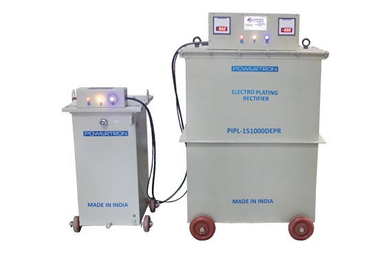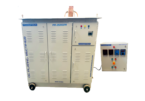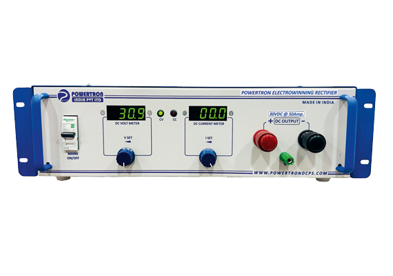

IGBT-ERP Controlled Electro-Plating Rectifier Manufacturers & Exporters
Powertron's IGBT Controlled Plating Rectifier (IGBT-ERP) is built for higher-power electroplating and electrochemical lines where independent voltage and current setting, active current sharing across modules, and endurance under continuous duty matter more than sheer compactness. Output voltage runs from 0–12VDC to 0–100VDC, with current customised to the process. This page covers features, specification, model options and how IGBT control compares to the MOSFET, thyristor and diode alternatives in Powertron's range.
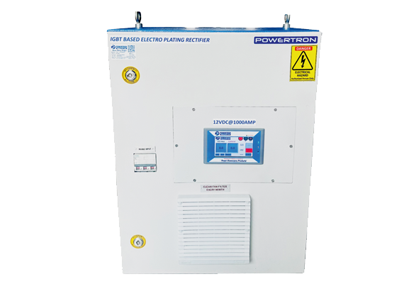

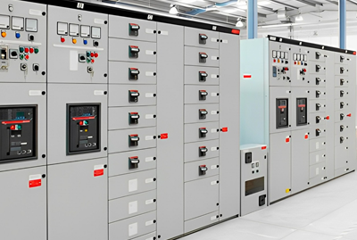





Technical Specifications — IGBT-ERP Controlled Electro-Plating Rectifier
| Parameter | Specification | What It Means For You |
|---|---|---|
| Output Voltage | 0–12VDC to 0–100VDC (standard bands) | Covers small-parts plating through higher-voltage electrochemical processes. |
| Output Current | Customisable to load, multi-module capable | Higher-current lines are served by paralleled, current-shared modules rather than one oversized stage. |
| Current Sharing | Active, across modules | Prevents one module from carrying a disproportionate share of load and failing prematurely. |
| Control | Independent voltage & current setting | Precise process control for plating chemistries with narrow current-density tolerances. |
| Protection | Short circuit / overload / overvoltage | Bath, busbars and modules are protected under fault conditions. |
| Duty Rating | Continuous, endurance-rated | Built for sustained production-line duty rather than intermittent use — the distinction that separates an IGBT-ERP unit from a lighter-duty rectifier. |
Model / Variant Table
| DC Output | DC Current |
|---|---|
| 0–12VDC | Customisable to load |
| 0–18VDC | Customisable to load |
| 0–24VDC | Customisable to load |
| 0–60VDC | Customisable to load |
| 0–100VDC | Customisable to load |
Range Quick-Selection Table
| Output Range Needed | Recommended Model |
|---|---|
| 0–24VDC, high current | High-throughput plating lines, automotive components |
| 0–24 to 0–60VDC | Industrial finishing, power generation & distribution equipment |
| 0–60 to 0–100VDC | Heavy-duty electrochemical and anodizing processes |
How It Works
The IGBT Controlled Plating Rectifier uses IGBT power modules — devices suited to higher current and power than MOSFETs — arranged with active current sharing, so that as more modules are paralleled to reach higher output current, each one carries a proportionate, monitored share of the load. This is what allows the platform to scale to production-line current levels without any single module becoming a reliability weak point.
Voltage and current are set and regulated independently, so an operator can hold a fixed plating voltage while limiting current (or vice versa) to match a specific bath chemistry's tolerance window. The manual current limit option gives an added layer of process control beyond the automatic overload protection. Because the unit is built for endurance duty, thermal design and component selection are rated for continuous, high-utilisation production rather than occasional use — the reason this variant is positioned above MOSFET and diode rectifiers for heavy-duty lines.
Applications by Industry
| Industry | Application | Load / Duty Character | Recommended Configuration |
|---|---|---|---|
| Power Generation & Distribution | Component and busbar plating | Continuous, heavy duty | 0–24 to 0–60VDC, high current, multi-module |
| Oil & Gas Refinery | Corrosion-protection plating on components | Continuous, harsh environment | 0–24 to 0–100VDC |
| Railways & Metro | Component plating for rolling stock parts | Continuous production | 0–24 to 0–60VDC |
| Industrial Automation | In-line plating within automated cells | Continuous, high uptime | Independent V/I control |
| Defence | Precision plating for defence-grade components | Continuous, high-reliability | Tight tolerance, custom current |
| Marine | Corrosion-resistant coatings for marine hardware | Continuous / harsh environment | 0–24 to 0–60VDC |
IGBT vs. Thyristor Controlled Plating Rectifier
| Criteria | IGBT Controlled | Thyristor Controlled |
|---|---|---|
| Switching approach | High-frequency IGBT switching | Line-frequency phase control (SCR) |
| Voltage/current independence | Fully independent setting | Coupled to phase-control characteristics |
| Current sharing at high power | Active, module-level sharing | Depends on transformer/module design |
| Response speed | Fast electronic response | Slower, tied to AC line cycle |
| Endurance duty rating | High, continuous production duty | High, proven for heavy industrial duty |
| Best fit | High-power lines needing precise V/I control | Heavy industrial loads, modular scalability |
| Typical current class | High, multi-module scalable | High, transformer-limited per module |
Manufacturing & Quality
Every IGBT Controlled Plating Rectifier is built at Powertron India's own manufacturing facility in Wagle Estate, MIDC, Thane (Maharashtra), where design, winding, assembly, and testing are carried out in-house rather than outsourced. Units go through a documented quality process before dispatch, and Powertron holds ISO, CE, BIS, and GeM empanelment credentials, with manufacturing recognised under the Make in India and MSME programmes. Beyond Thane, Powertron supports customers through sales offices in Delhi, Pune, Hyderabad, Bengaluru and Tamil Nadu, and serves export markets through international sales offices in Dubai, Singapore and Malaysia. Post-installation, the same team that engineers the unit is available for commissioning support, spares, and after-sales service, so buyers are not left dealing with a reseller once the order ships.
FAQ
IGBT devices handle higher current and power more efficiently, making this variant suited to heavier-duty, higher-current plating lines than the MOSFET version.
When multiple power modules are paralleled to reach high output current, active current sharing ensures each module carries a proportionate load, preventing any one module from being overstressed.
Yes, independent voltage and current setting is a standard feature, which supports plating processes with tight current-density requirements.
Yes, operators can set a manual current limit directly, in addition to the automatic overload protection.
0–12VDC up to 0–100VDC in standard bands, with current customised to your process.
Yes, it's built for endurance performance under continuous, high-utilisation production-line operation.
Power generation & distribution, oil & gas, railways, industrial automation, defence and marine applications with heavier current or reliability requirements.
Yes, additional paralleled, current-shared modules can be added to reach higher output current.
Short circuit, overload and overvoltage protection are standard.
Send your required output voltage, current and duty cycle to sales@powertrondcps.com or call the numbers listed above.
Need a IGBT-ERP Controlled Electro-Plating Rectifier?
Request a quotation for a IGBT-ERP Controlled Electro-Plating Rectifier. Send your required DC output voltage and current to sales@powertrondcps.com or call +91 8097707496 / +91 7208560460 — most plating rectifier quotations are returned once load and process details are confirmed.