

DC Telecom System Manufacturers & Exporters
Powertron's DC Telecom System is a modular 48VDC power plant built for cellular base stations, telecom data centres and remote communication hubs that need round-the-clock, redundant DC power. Output power runs from 6.4KW up to 32KW across standard variants, with hot-swappable rectifier modules and N+1 redundancy so a single module failure never interrupts the site. This page covers features, technical specification, the full model matrix, and how to select the right configuration for your network.
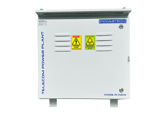




Technical Specifications — DC Telecom System
| Parameter | Specification | What It Means For You |
|---|---|---|
| Output Voltage | 48VDC (telecom standard) | Direct compatibility with existing BTS, node and data centre DC busbars. |
| Output Power (Ultimate / Loaded) | 6.4KW/3.4KW up to 32KW/20KW, or custom | You size the plant to present and near-term future load, in one product family. |
| Redundancy | N+1, hot-swappable modules | A module failure or planned swap does not interrupt site power. |
| Battery Support | VRLA or Lithium (LFP) | Choice of chemistry based on cycle life, weight and space constraints at site. |
| Design | Rack-mount, scalable | Capacity can be added in the field as network load grows, without re-engineering the shelter. |
| Monitoring | Real-time, remote-capable | Power, battery status and system health are visible without a truck roll — the detail that separates a telecom-grade plant from a generic industrial rectifier. |
Model / Variant Table
| Output Voltage | Output Power (Ultimate) | Output Power (Loaded) | Battery Backup |
|---|---|---|---|
| 48VDC | 6.4KW | 3.4KW | VRLA / Lithium (LFP) |
| 48VDC | 16KW | 8KW | VRLA / Lithium (LFP) |
| 48VDC | 24KW | 12KW | VRLA / Lithium (LFP) |
| 48VDC | 32KW | 20KW | VRLA / Lithium (LFP) |
| 48VDC | Custom | Custom | Custom — contact sales |
How It Works
A DC Telecom System is built around parallel rectifier modules that convert AC mains into regulated 48VDC, feeding both the connected telecom load and a battery string simultaneously. Because the modules operate in parallel with N+1 sparing, the system continues supplying full rated power even if one module fails or is pulled for maintenance — the remaining modules automatically absorb the load, and a technician can hot-swap the failed unit without a planned outage.
The battery bank (VRLA or lithium) is float-charged continuously and switches to full discharge duty the instant AC input is lost, with power distribution and monitoring circuits managing which loads draw from which battery string in extended outages. A supervisory monitoring and control layer tracks module health, battery state of charge, and power consumption in real time, and can alert or report remotely — which is what allows telecom operators to run these plants unattended at cell sites and remote hubs while still meeting 24/7 reliability targets.
Applications by Industry
| Industry | Application | Load / Duty Character | Recommended Configuration |
|---|---|---|---|
| Telecom / Cellular | Base station and node DC power | Continuous, 24/7, N+1 | 48VDC, 6.4–24KW ultimate |
| Data Centres | Auxiliary/edge DC distribution | Continuous, high availability | 48VDC, 24–32KW ultimate |
| Oil & Gas | Remote site communication power | Continuous, harsh environment | 48VDC with extended battery backup |
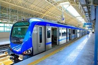
| Railway / Metro | Trackside and station comms power | Continuous | 48VDC, rack-mount |
| Defence | Field and fixed comms infrastructure | Continuous, ruggedised | 48VDC, custom enclosure |
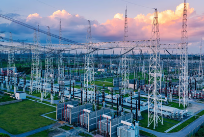
| Power Utilities & Substations | SCADA and comms auxiliary power | Continuous, mission-critical | 48VDC with N+1 redundancy |
Modular DC Telecom System vs. Conventional Fixed Rectifier
| Criteria | Modular DC Telecom System | Conventional Fixed Rectifier |
|---|---|---|
| Redundancy | N+1, hot-swappable modules | Single unit — failure means downtime |
| Maintenance | Swap a module live, no outage | Requires planned shutdown to repair |
| Scalability | Add modules as load grows | Fixed capacity; oversizing needed upfront |
| Monitoring | Real-time remote visibility | Often local indication only |
| Efficiency at partial load | Modules share load efficiently | Fixed-size unit runs inefficiently under-loaded |
| Battery integration | Charging & backup managed as one system | Often a separate charger/battery specification |
| Footprint | Compact, rack-mount, scalable | Sized for maximum capacity from day one |
Manufacturing & Quality
Every DC Telecom System is built at Powertron India's own manufacturing facility in Wagle Estate, MIDC, Thane (Maharashtra), where design, winding, assembly, and testing are carried out in-house rather than outsourced. Units go through a documented quality process before dispatch, and Powertron holds ISO, CE, BIS, and GeM empanelment credentials, with manufacturing recognised under the Make in India and MSME programmes. Beyond Thane, Powertron supports customers through sales offices in Delhi, Pune, Hyderabad, Bengaluru and Tamil Nadu, and serves export markets through international sales offices in Dubai, Singapore and Malaysia. Post-installation, the same team that engineers the unit is available for commissioning support, spares, and after-sales service, so buyers are not left dealing with a reseller once the order ships.
FAQ
48VDC, matching the standard used across telecom base stations, fibre nodes and data centre DC distribution.
One additional rectifier module beyond what's needed for full load is always running, so a single module failure doesn't interrupt power to the site.
Yes, modules are hot-swappable — a technician can pull and replace a failed unit while the system continues supplying full load from the remaining modules.
Ultimate power is the system's maximum rated capacity; loaded power is a typical operating point under normal site load — sizing decisions should account for both figures.
Yes, the system supports both VRLA and lithium (LFP) battery strings; lithium is often chosen for reduced weight and longer cycle life at remote sites.
Real-time monitoring and control capability is a core feature of the platform; confirm your specific NMS/SNMP integration requirement when requesting a quotation.
Yes, Powertron provides fully customised solutions above the standard variant range — share your load requirement with sales.
Yes, with appropriate enclosure and thermal management specified at the time of order — confirm site environment when enquiring.
ISO, CE, BIS and GeM empanelment, with manufacturing recognised under Make in India and MSME — full certification images are available on request.
Send ultimate/loaded power requirement, redundancy needs, battery preference and site environment to sales@powertrondcps.com, or use the Request a Quote button above.
Need a DC Telecom System?
Request a quotation for a DC Telecom System. Share your site's ultimate power requirement, redundancy needs, and battery preference at sales@powertrondcps.com or call +91 8097707496 / +91 7208560460 for a configuration-matched quotation.